
Parshall flume is a flow rate device with a wide range of application. It can be used for
flow measurement in creeks, irrigation and/or drainage channels, sewer outfalls, Waste Water Treatment Plants,
etc. Main advantages can be summarised as follows:
..........a) A relatively low energy loss(3-4 times lower than in sharp-crested
weirs).
..........b) A small sensitivity to a velocity distribution in an approach
channel.
..........c) Flow rate measurement even under drowned conditions.
..........d) Velocities inside Parshall flumes are high enough to prevent them
from the deposition of sediments
...............or accumulation of debris.
..........e) Minimum maintenance requirements.
..........f) A wide range of flow rates.
..........
h) A long lifetime.
The flow rate measurement is based on the assumption that the critical flow is produced by constricting the width in the throat and then raising the bottom. The flow changes from subcritical to supercritical and then the measurement of a single depth is sufficient to determine the discharge. The water level is measured and recorded either in the center line of the approach channel using an ultrasonic level sensor or inside a stilling manhole (which can be a part of Parshall flume) by means of a float with a mechanical transfer to a flow rate, or using a sensor with an electronic unit. The electronic unit transforms the measured flow depth to a flowrate.
Technical data
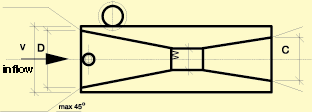
Parshall flume is made of polypropylene and it is not commonly equipped with a float manhole. Precise dimensions and flume weights are shown in Table 1. These dimensions are compulsory for a site design, however some flume parts and a float manhole can be changed. Equation (1) is used for the flow rate calculation when the flow depth is recorded inside a stilling manhole or at the channel section B. When using ultrasound sensor, a more suitable section profile B� is located before the throat, see Figure 1, and a different rating curve is provided by the supplier. Parshall flumes have been verified by the Czech Metrology Institute in June 1, 1995 under a certification No TCM 142/95-2075. A maximum uncertainty of +/-1.5% of actual flow rate is achieved. Due to a larger uncertainty in the field measuring conditions, we guarantee +/- 3% of actual flow rate.
|
P1
|
P2 | P3 | P4 | P5 | P6 | P7 | P8 | P9 | |
| Qmin | 0,26 | 0,52 | 0,78 | 1,52 | 2,25 | 2,91 | 4,4 | 5,8 | 8,7 |
| Qmax | 6,22 | 15,1 | 54,6 | 168 | 368 | 598 | 898 | 1211 | 1841 |
| a | 0,0609 | 0,1197 | 0,1784 | 0,354 | 0,521 | 0,675 | 1,015 | 1,368 | 2,081 |
| b | 1,552 | 1,553 | 1,555 | 1,558 | 1,558 | 1,556 | 1,560 | 1,564 | 1,569 |
| B' | 30 | 34 | 39 | 53 | 75 | 120 | 130 | 135 | 150 |
| Z Qmin % Qmax |
5,4 | 4,1 | 4,1 | 4,1 | 3,8 | 3,8 | 3,6 | 3,6 | 3,5 |
| 4,8 | 3,6 | 3,6 | 3,6 | 3,2 | 3,2 | 3,1 | 3,1 | 3,0 | |
| hd/ha | 0,6 | 0,7 | |||||||
| m | 9 | 10,6 | 19,1 | 49,0 | 81,0 | 146 | 183 | 231 | 252 |
| W | 2,54 | 5,08 | 7,62 | 15,24 | 22,86 | 30,48 | 45,70 | 61,00 | 91,40 |
| C | 9,29 | 13,49 | 17,80 | 39,4 | 38,1 | 61,0 | 76,2 | 91,44 | 121,9 |
| D | 16,75 | 21,35 | 25,88 | 39,69 | 57,47 | 84,46 | 102,6 | 120,7 | 157,2 |
| E | 23 | 26,4 | 46,7 | 62,0 | 80 | 92,5 | 92,5 | 92,5 | 92,5 |
| L | 63,5 | 77,5 | 91,5 | 152,4 | 162,6 | 286,7 | 294,3 | 301,9 | 316,9 |
| O | 5 | 5 | 5 | 10 | 10 | 10 | 10 | 10 | 10 |
| S | 20 | 20 | 20 | 20 | 20 | 20 | 20 | 20 | 20 |
| U | 24,8 | 26,8 | 49,2 | 69,6 | 87,6 | 101,1 | 101,1 | 101,1 | 101,1 |
| V | 30,7 | 35,35 | 39,9 | 54 | 80 | 100 | 120 | 140 | 180 |
Rating curve for a depth ha inside a stilling manhole:
Q = a * hba ... [m3/s,m] /1/
ha ... flow depth in the distance B before the throat [m]
Equation for discharge in case that the flow depth is measured at a distance B� can be sent to the client.
Checking the drowned conditions:
The actual value of a ratio hd to ha must be lower than the values specified in Table 2
ha ... flow depth at a distance B before the throat [m],
hd ... water depth behind the flume, see Figure 1 [m],

|
|
|
|
|
|
|
|
|
|
|
|
|
|
|
|
|
|
|
|
|
|
|
|
|
|
|
|
|
|
|
|
|
|
|
|
|
|
|
|
|
|
|
|
|
|
|
|
|
|
|
|
|
|
|
|
|
|
|
|
|
|
|
|
|
|
(flow rates are given in l/s)
Operational conditions
Parshall flumes are made of polypropylene and are designed to measure for water flow measurements. The flume is resistant to air temperatures (up to 80 oC), however, water inside the flume must not get frozen. Moreover, Parshall flume can stand up well the solutions of inorganic salts, acids and bases that do not exhibit strong oxidation properties, and a majority of organic solvents. It is recommended once a year to clean a stilling manhole and a connecting pipe between the flume and the manhole. In flows carrying sediments, it is recommended to carry out the inspection and maintenance more often. Maximum size of suspended solids is limited to 80% of the throat width (dmax = 0.8 w).
Determination of flow in Parshall flumes
In order to transform the measured depth to the flow rate, the following approaches are
available:
a) mechanical without a data recorder,
b) electronically with data recording
Mechanical flowmeter
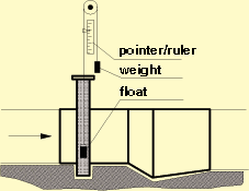
A float made of polypropylene and/or glass is located inside a stilling manhole and
connected by a wire with a weight. A pointer attached to the wire indicates a current discharge. The measuring
device shown in Figure 2 serves only as a low-accuracy flow meter and should not be used as a measuring
standard. The mechanical transmission device is not a part of the flume package and needs to be ordered
separately.
Electronic flowmeter
The electronic unit consists of a sensor and a microprocessor-based evaluation unit. The
unit enables not only to determine the flow depth and discharge but also a data storage, statistical analysis,
regulation of a pump operation etc. as well as a link to PC, see Appendix.
The ultrasound transducer is located in the centre line of the flume, see Figure 1. The
sensor is placed 20 cm above a maximum water level and the unit itself is usually placed inside the building.
As an option, Parshall flume can be equipped with a brass depth gauge, see Figure 3, fixed
on the flume wall. Recorded depth of flow can be used for a direct determination of the flowrate and
comparison with the electronic unit discharge.
 ..........................
 .........................
(c) 2003, PARS Aqua, s.r.o.